|
General information of twist drills |
The twist drill is the most common type of drill. The shank of the drill is held by the machine tool, which in turn imparts a rotary motion. This shank may be straight or tapered. The body of the drill is typically made up of two spiral grooves known as flutes, which are defined by a helix angle that is generally about 30 degree but can vary depending on the material properties of the workpiece. The point of the drill generally form a 118° angle and includes a 10 degree clearance angle and chisel edge .The chisel edge is flat with web thickness of approximately 0.015 x drill diameter. This edge can cause problems in hole location owing to its ability to "walk" on a surface before engaging the workpiece. In the case of brittle materials, drill point angles of less than 118 are used, while ductile materials use larger points angles and smaller clearance angles.
Main technical conditions of twist drill
Dimensions
Drill diameter
The values indicated in the relevant dimensional standards apply in respect of the diameter of twist drills.
Test point: on the lands at the corners
Testing equipment: micrometer
Tapering of diameter
The diameter of twist drills usually reduces from the drill tip towards the shank in the area of the flutes.
Test values: The taper on diameter amounts to 0.02 to 0.08mm over a length of 100mm
Test point: at the outside diameter on the land.
Testing equipment: micrometer and indicating measuring instruments.
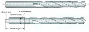
Straight shank
Tolerance for shank diameter f11, tolerance for roundness and parallelism 0.02mm for the shank length.
Concentricity tolorance
The concentricity tolerance of the twist drill is calculated from the equation.
Tr=0.03+0.01*L/d
in which "L" is the total length and "d" the diameter of the drill (all dimensions in mm)
Length
The tolerance of lenght for the total length corresponds for the degree o accuracy "very coarse" according to DIN 7168 part 1. The flute lengths giver in the relevant dimensional stands are minimum dimensions.
Point angle
Test value: 118°or 135º
Test point: at the cutting edges
testing equipment: universal bevel protractor indicating measuring instruments.
Materials and hardness
materials: M2, M35, M42, W9Mo3Cr4V, W4Mo3Cr4V
hardness: HSS HRC63-66; HSS-E HRC64-68
Test point: on outside diameter on the land or adjacent relieved land
Test equipment: hardness tester
Marking
Twist drills with diameter 3mm and upwards shall be marked with
Diameter; material; name or mark of manufacturer
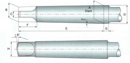
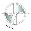
Twist drill with straight shank
 figure
1
figure
1Twist drill with taper shank
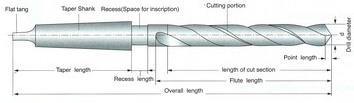 figure
2
figure
2General dimensions of Morse taper shanks
figure
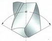
3Cutting portion
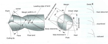 figure
4
figure
4In the context of cutting technology, land width b is the body clearance land width which is to be by b see DIN 6581.
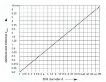
Web thickness K
Test values: the web thickness according to the figure 5 showed as below shall not be less than the minimum value indicated in the figure 6.
 |
 |
| figure 5 | figure 6 |
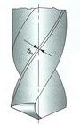
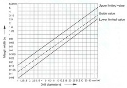
Margin width b
Test values: the land width as in figure 7 shall lie within the limitting values indicated in the figure 8.
Test point: 5mm behind the corner
Testing equipment: slide gauge
 |
 |
| figure 7 | figure 8 |
Angle on twist drills
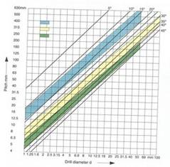
A helix angle
Recommended test value: recommended ranges depending on the tool types N, H and W according to DIN 1836 and the diameter of the drill included in figure 9.
Test point: at the corner
Testing equipment: according to VDI Guideline 3331 part 1, section margin width b.
 |
 |
| figure 9 | figure 10 |
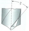
B point angle
Test value: usual executin for tool types N and H: 118, for tool type w:130
test point: at the cutting, see figure 11
testing equipment: according to VDI Guideline 3331 part 1, section margin width b.
 figure
11
figure
11
(1)Drills are worn off irregularly. It should be sharpened prior to developing into excessive wear.
(2)Resharpening
a Grind the correct point angle to suit your application-(figure12)
b Check that both cutting lips have the same angle. On a 130 degree point,
each lip should be 65 degree toward the
axis. The point must be on center, i.e., the chisel edge must produce cutting
lips of equal length(figure12).
Grind primary relief and Secondary clearance,(figure9)
c Grind web thinning(figure12)
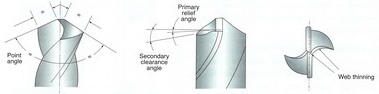 figure
12
figure
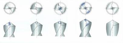
12Web thinning
A Without thinning
Suitable for drill of general purpose. Thanks to thin web thickness, web thinning
is not need.
This without web thinning type is applied to design of drills for mild steel,
alloy stee|, cast iron, stainless steel, titanium, inconel, etc. and
conventional cutting conditions.
B Type c thinning (DIN1412 FORM C, SPLIT
POINT)
Because Split point enables good centering when drilling and breaks .the chips,
chip removals is easy-
Suitable for dri11 design in high hardened tough materials, i.e, heat treated
steel, titanium alloy, stainless steel,i ncoroy inconel, nimonic, etc.
C Type R thinning (HELICAL THINNING)
Helical thinning ensure to frequent chip breaking and removal. The different
direction force of cutting edges and helical thinning pa 同 s enables that chips
curl, break and remove through the flutes. ln addition helical thinning makes
the chip room up to center, remove the chisel and enables good centering.
D Type A thinning (DtN1412FORM A)
A type thinning makes thin chisel, good chip removal and favorable centering.
This type is the easiest type to grind the thinning. ln narrow web and wide
fluted drills, keeping of the rigidity and smooth chip removal are possible-
E Type B thinning(DIN1412FORM B)
ln case of work materials with low cutting resistance and good chip removal, ie,
cast iron, aluminium, plastic etc, B type thinning is suitable.
Especially when drills for high hardended steels are designed, this type is
applied to decrease rake angle and avoid chipping of cutting lips.
 |
||||
| A | B | C | D | E |
figure 13